Express VI
What Are Express VIs?
Express VIs are equipped with a configuration dialog box that allows users to set input parameter values directly while editing the VI. They are purposefully designed to streamline programming for common tasks. For typical LabVIEW programming patterns, such as data acquisition or performing frequency domain transformations on waveforms, one or two Express VIs with some straightforward configuration can suffice. To facilitate easy access for programmers, LabVIEW includes the most commonly used Express VIs in the "Express" section of the function palette. Meanwhile, some of the more complex and less frequently used Express VIs are categorized into other sub-palettes based on their functionality.
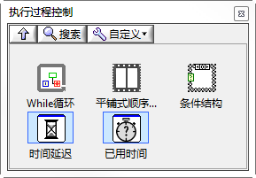
One can easily distinguish Express VIs from regular VIs on the function palette by the light blue border around their icons, as seen in the "Time Delay" and "Elapsed Time" VIs below.
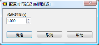
The usage of Express VIs diverges from that of regular VIs as well. Typically, Express VIs feature a configuration dialog box (as shown below), which facilitates the setting of necessary data for the Express VI's operation, thereby removing the need for direct data input on the block diagram. This significantly declutters the block diagram. Express VIs usually offer more robust functionality compared to standard VIs. For instance, basic programs for data acquisition and display can be easily achieved using just a few Express VIs, thanks to their simplicity and user-friendly nature, thus earning the name "Express VIs".
Despite the powerful features and convenience offered by Express VIs, they come at the cost of lower efficiency. In applications with simple functionality, the Express VIs employed may include an array of unneeded features. These superfluous functionalities not only take up memory space but also slow down the program's execution. Consequently, for efficiency-critical applications, Express VIs may not be the best choice.
How Sub VIs Appear on the Block Diagram
Standard sub VIs, when placed on the block diagram, default to being displayed as icons. In icon mode, you can opt to "Show Terminals" via the right-click menu to reveal its connector pane. An alternative display style available is the expandable node, which can be activated by deselecting "Show as Icon" in the sub VI's right-click menu. Sub VIs shown as expandable nodes allow for all their terminals to be moved and listed by dragging the diagram's bottom border line (as seen with the sub VI on the right in the image below).
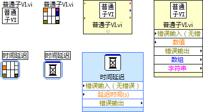
Like standard sub VIs, Express VIs also support these various display modes. However, Express VIs are by default shown as expandable nodes and always feature a blue border background, regardless of the chosen display style.
Sub VIs displayed as expandable nodes take up more screen space but have several benefits: they display the names of the terminals, improving program readability; the expandable style for Express VIs is collapsible, allowing terminals not in use to be minimized. The expanded terminals are spaced out, facilitating the differentiation between numerous wires and terminals, particularly when the VI has many terminals.
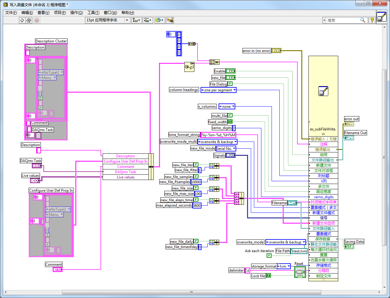
Take the "ex_subFileWrite.vi" sub VI shown below as an example. It has a multitude of input and output parameters. Utilizing the expandable node display method clearly illustrates the connections for each parameter. If displayed as an icon, distinguishing the connections between parameters would be virtually impossible.
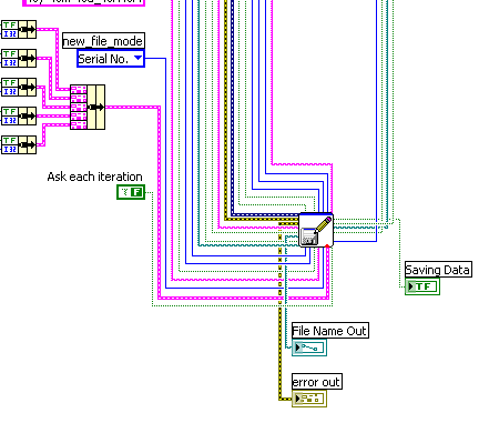
Understanding Express VIs
Standard sub VIs come with both a front panel and a block diagram, where the front panel controls define the parameters used by the VI, and the block diagram contains the code that executes its functions. In a VI's block diagram, double-clicking on a standard sub VI's icon opens its front panel; if you hold the Ctrl key and double-click, it opens both the front panel and block diagram.
Express VIs, however, operate differently from standard sub VIs. Double-clicking an Express VI's icon on the block diagram launches a configuration dialog box instead. Typically, standard sub VIs are developed by programmers themselves, necessitating the opening of the sub VI's front panel and block diagram for edits, modifications, and debugging. Express VIs, usually provided with LabVIEW or its toolkits, don't require developers to create or modify them, often eliminating the need to access their internal code. An Express VI integrates multiple functions, enabling programmers to easily configure it through its dialog box to suit their specific requirements.
The block diagram of a standard sub VI is stored in a .vi file. For such VIs, the executed code remains the same regardless of where or how often it is called within an application, running the block diagram contained in the .vi file. Express VIs, however, do not adhere to this rule. Programmers can alter the configuration dialog box as needed, and any change in configuration modifies the Express VI's execution code. Thus, the same Express VI called in different contexts may execute different code, meaning its block diagram isn't stored in a single .vi file. Actually, the block diagram of an Express VI is saved within the .vi file of the VI that calls it. For example, if a VI named A.vi calls an Express VI named B, B's block diagram is saved within A.vi. However, double-clicking B's icon won't directly reveal its block diagram.
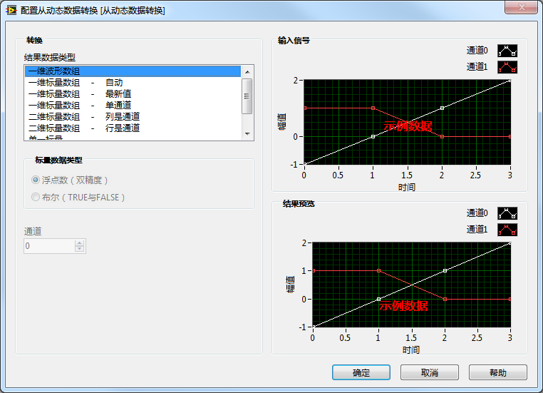
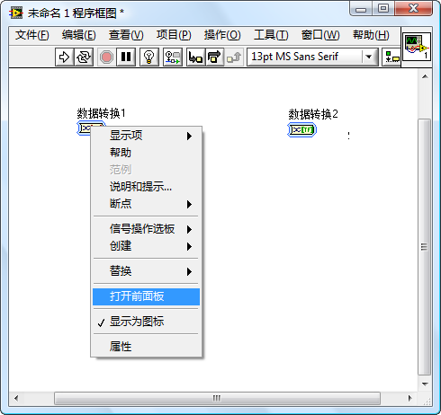
While some Express VIs allow viewing of their block diagrams (and others do not), selecting "Open Front Panel" from an Express VI's right-click menu converts it into a non-configurable standard sub VI, solidifying its code. This action grants access to the front panel and block diagram. Take the "Convert from Dynamic Data" Express VI as an example (found under "Express --> Signal Operations --> Convert from Dynamic Data"). When placing two such Express VIs on a block diagram, named "Data Conversion 1" and "Data Conversion 2", and configuring them differently:
"Data Conversion 1" is set to "1D Waveform Array":
Upon converting the Express VI into a standard VI and viewing its block diagram:
The block diagram consists of a straightforward sub VI:
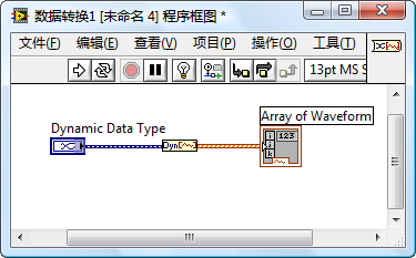
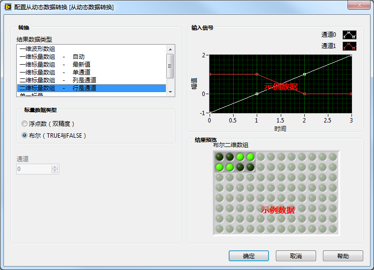
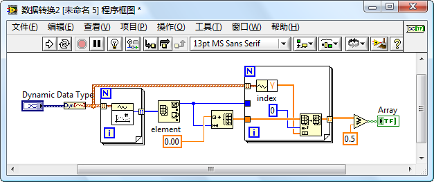
"Data Conversion 2" is configured for "2D Scalar Data" with the scalar data type set to "Boolean". Viewing its block diagram reveals a completely different structure from "Data Conversion 1" due to the differing functions they perform.
Express VIs Tailored for Test Programs
Test programs represent a prevalent type of LabVIEW application, prompting LabVIEW to specifically offer a wide array of Express VIs designed for these programs. These include Express VIs for tasks such as data acquisition/generation, analysis, display, and storage:
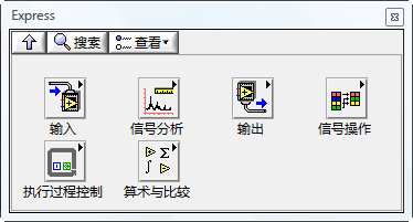
LabVIEW streamlines the work for programmers by integrating functionalities commonly utilized in testing into a few highly capable sub VIs. The complexity of a sub VI's functions directly correlates with the diversity of data it necessitates. Typically, configuring a few simple parameters suffices for a specific program's needs.
For example, generating waveform data is a frequent requirement in programs. Thus, LabVIEW offers a sub VI dedicated to waveform generation. Creating a waveform demands extensive information from the programmer, such as type, frequency, amplitude, phase, sampling rate, and sample count, among many others. Implementing these functionalities through standard sub VIs would overwhelm the block diagram and diminish the program's readability. Moreover, it complicates programming by making it difficult to predefine every data point before program execution.
However, not all of these parameters need to be variable in certain specific applications. Often, a program only requires generating a fixed waveform type or specific frequencies and amplitudes. That is, the program only utilizes a fraction of the available functionality. Using a complex VI for such tasks not only feels like overkill but also becomes cumbersome due to the multitude of parameters involved.
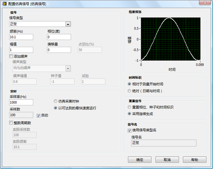
Express VIs emerged to bridge this gap. They feature a configuration dialog box that allows users to easily select the data needed. Placing an Express VI on the block diagram or double-clicking an existing one brings up its configuration interface, complete with instructions to assist programmers in choosing appropriate configuration data. Some interfaces, like that of the Simulate Signal Express VI, even include a "Result Preview" feature, enabling programmers to see the effects of their parameter selections in real time without having to run the entire program.
Below is the "Simulate Signal" Express VI’s configuration dialog box. Altering parameters such as frequency and amplitude immediately reflects changes in the simulated signal waveform in the "Result Preview".
About Setting the Sampling Rate
Higher sampling rates demand more computing and storage resources. When setting a sampling rate, it's important to weigh the device's capabilities. On the flip side, a sampling rate that's too low may miss critical signal details (high-frequency components). According to Shannon's sampling theorem (Nyquist sampling theorem), the sampling frequency should be at least twice the maximum frequency in the analog signal's spectrum to avoid distortion. For a pure sine wave, which consists of a single frequency, the sampling rate need only be slightly more than twice that frequency. Other waveforms, like a perfect square wave, have infinitely high high-frequency components, but sampling rates cannot be infinitely high. High-frequency bands often carry less critical information, so perfectly reconstructing the original signal after sampling isn't always necessary; it suffices to accurately reconstruct the most significant frequency bands. For imperfect sine waves, a sampling rate marginally above twice the fundamental frequency might result in excessive distortion. Finding the most suitable sampling rate requires aligning with project demands. If starting from scratch, setting the sampling rate to ten times the fundamental frequency and adjusting as needed can serve as a practical approach.
Applications
Utilizing NI's data acquisition devices in conjunction with Express VIs simplifies the creation of standard test programs considerably. Essentially, each major step - acquisition, processing, display, and storage - typically requires just one or two Express VIs.
For instance, with the "DAQmx" software package installed, you can employ the "DAQ Assistant" Express VI for data acquisition:
This Express VI offers a wizard-style configuration dialog box that methodically guides users through the process of selecting and setting up NI hardware for signal acquisition:
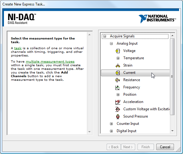
Users first select a type of signal to measure. The wizard then presents compatible hardware options. After selecting the hardware, it's configured as needed.
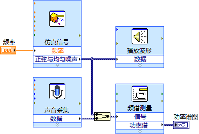
Although not every computer is fitted with the same model of NI data acquisition card, most have a sound card. Sound cards function as signal input/output devices, making them suitable examples for data acquisition program demonstrations in this book. Using sound cards, programming with Express VIs is just as straightforward. The goal here is to implement a program that generates a sine wave, outputs this wave through the computer speakers as sound, captures this sound signal with a microphone, and then compares the differences in power spectra between the original and captured waveforms.
The program involves four key steps: generating the waveform signal, outputting the signal, capturing the signal, and calculating the signal's power spectrum. These steps can be executed using just four Express VIs. The program's block diagram is depicted below:
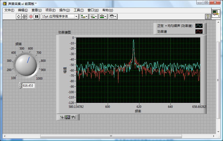
The next image illustrates the program's output. On the power spectrum display, the original signal is shown in blue (lighter color), and the signal captured via the microphone appears in red (darker color). It's clear that the recaptured signal, while matching the original in frequency, shows a decrease in power and an increase in relative noise.
When configuring these Express VIs, it's crucial that the length of the simulated signal corresponds with the duration of the sound capture to prevent the inclusion of additional irrelevant signals in the captured data.
Programming with Express VIs might be straightforward, but their functionalities are inherently limited to those most frequently utilized in test programs. If a program has specific requirements or if devices and data acquisition cards from other manufacturers are used, employing more specialized, lower-level VIs for programming may become necessary.
Advantages and Disadvantages of Express VIs
The primary advantage of Express VIs lies in their ability to make programming more accessible. Many LabVIEW users do not have a background in computer software or related fields, and they might find writing complex programs challenging. Utilizing Express VIs to achieve certain functionalities often involves simply selecting a few parameters in a configuration panel, which is undoubtedly easier than coding directly on the block diagram.
However, Express VIs have two main drawbacks. First, the available selection of Express VIs is limited, covering only a subset of the common functionalities needed for testing and measurement. It is impractical to rely solely on Express VIs for the entirety of a project's needs. Second, they are less efficient in execution compared to standard VIs. Despite an application only requiring a fraction of an Express VI's capabilities, the inclusion of its additional functionalities means that the compiled executable code for programs utilizing Express VIs tends to be larger and slower than those employing standard VIs.
Creating Your Own Express VI
In addition to the built-in Express VIs provided by LabVIEW, programmers also have the option to create their own Express VIs. Starting from LabVIEW 8.6, accessing the menu item "Tools -> Advanced -> Create or Edit Express VI" opens a dialog box titled "Create or Edit Express VI". This dialog box offers step-by-step guidance for crafting an Express VI.